P6X Pulse Settings
The P6X family of devices provide a range of Pulse I/O capabilities, defined as follows.
Connector
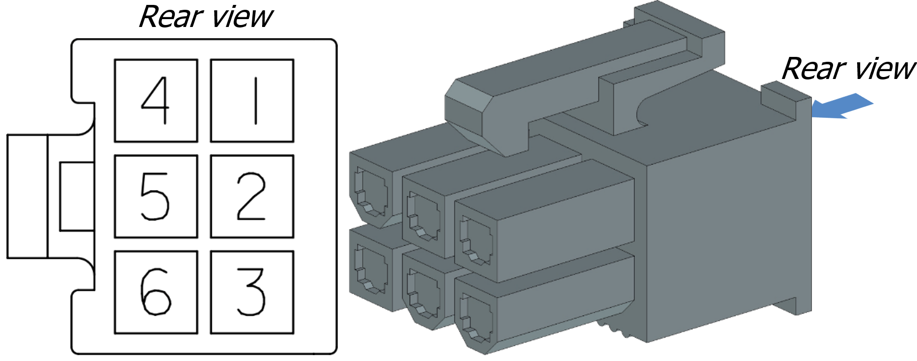
The Pulse implementation on the P6X uses the TX and RX pins from the MDB port. This port is also used to provide the P6X terminal with power. The part number for this component is Molex 39-28-1063.

The MDB port on the P6X terminal
The connector that should be plugged into the port is as follows. This component has part number Molex 39-01-2060 and should be used with crimp contacts Molex 39-00-0065.
The connector to connect with the MDB port
Pinout
The MDB Connector has the following pinout:
(Master Receive) Pulse output – Pin 4
(Master Transmit) Pulse input – Pin 5
(Pulse I/O) Isolated GND – Pin 6
Pin 1 – Vin (12 – 24 VDC)
Pin 2 – GND (power)
Pin 3 – Not Connected
The Pulse output and input have their own ground (isolated GND), as they are galvanically isolated from the rest of the terminal. This also means that a completely different Power Supply can be used for the Pulse output and input.
Pulse Output
When the terminal is configured with the Pulse output option, a valid transaction will automatically trigger a response on the pulse output. The pulse output can be configured to fit the needs of a variety of applications.
Electrical
The output pulse is created by an optocoupler, which pulls the applied voltage to the isolated ground. This applied voltage can range from 3.3V to 24V. If designed correctly higher voltages are possible, but not recommended. 70V is the absolute maximum voltage the optocoupler can support. The maximum sink current of the optocoupler is 12.5 mA, so an appropriate pull-up resistor should be chosen (see Typical application for a how-to).
Configurability
The output pulse can be configured to send 1 or multiple pulses for each transaction.
The pulse output can also be configured to be normally open or normally closed. However, as an optocoupler is used, the output will always be in a normally open state until the terminal has booted. If a normally closed configuration is chosen, this could lead to a single pulse being registered when the terminal is booting.
The duration of a pulse can be configured from 1ms to 49 days with increments of 1ms.
The figures below show 2 examples of how the pulse output can be configured. The settings that need to be set can be found in Pulse settings within the MyPayter terminal management system.
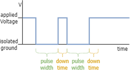
Pulse output configured for normally open with 2 pulses per transaction
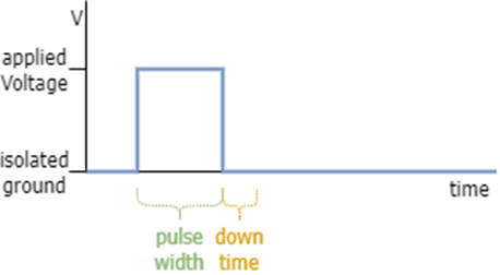
Pulse output configured for normally closed with 1 pulse per transaction
TLDR
Optocoupler driven
3.3V – 24V recommended Voltage
70V absolute maximum Voltage
12.5mA maximum sink current
1 or more pulses per transaction
Normally open or normally closed configurable
Normally closed can give an invalid pulse during boot
1ms to 49 days pulse duration
Typical Application
Digital Signal
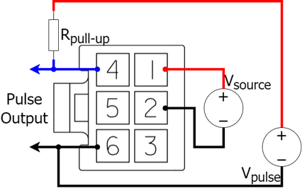
The figure below shows the typical application. It is advised to choose 1mA as the sink current for the P6X pulse output pin. This will result in a voltage over the pulse output pin of approximately 0V. The voltage over the resistor will then be the entire source voltage. With these values we can calculate the resistor value to achieve this scenario:

In the case that the P6X is powered with 12V, the pull-up resistor will be 12kΩ. While for a power source of 24V will it be 24kΩ.
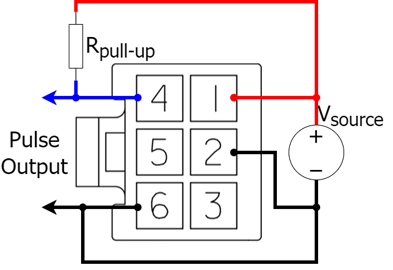
Typical application for pulse output using the power source
There might be cases where it is preferred to have the pulse work from a separate power supply. For example, when the P6X is powered by another power supply then the device which needs the pulse. Or when the 5V supply is used. This is possible because of the optocoupler. The application for such a case can be seen in the figure below. The pull-up resistor will now be calculated according to the voltage of Vpulse and not Vsource. The same calculation applies.
Typical application with separate power supply for pulse
Using the digital signal to switch a load
In some cases, control of a higher current load might be required, for example an electric motor. However, keep in mind that using such a method does not allow feedback, therefore product release or service provision might not be guaranteed. When controlling a higher current load, is it recommended to use a P-channel MOSFET to switch that load. The P-channel MOSFET can be used with separate power supply configuration, where the separate power supply should be the same as the supply used for the load. The final schematic can be found in the figure below.
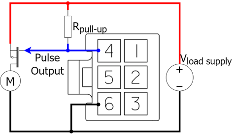
Using the pulse output to switch an electric motor, a high current load
This leaves choosing a P-channel MOSFET. There are 2 characteristics that need to be considered: Id (maximum drain current), Vds (breakdown voltage). Id should be bigger than the current drawn by the motor for the source voltage applied. Vds should be higher that the supply voltage.
Pulse Input
This input pulse can be used to detect a high or low input signal.
Electrical
Just like the output is the pulse input implemented with an optocoupler, so it is similar to controlling an LED. As long as the voltage stays below 0.7V the input will be considered as low. A voltage from 3.3V to 5V on the input pin will be considered as high.
The current that the input will draw for the voltage over it can be seen in the figure below. From this graph we can see that the current at 3.3V is 10.5mA and for 5V is 18.8mA.
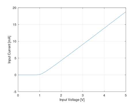
IV curve of the Pulse input
Configurability
The terminal can be configured to use the pulse input in 2 separate ways: ‘terminal inhibit’ or ‘count pulses’.
With ‘terminal inhibit’ mode the terminal will not allow transactions when the input is either high or low (depending on the configuration). This is useful for devices that take time before a new pulse can be accepted. It can also be used when a device is out of order.
In ‘count pulses’ mode the terminal will record each pulse it sees. This mode is not supported as standard as it only logs the pulses and nothing more.
TLDR
Optocoupler driven
0V – 0.7V on input is low
3.3V – 5V on input is high
Input value is configurable to invert
2 modes: ‘terminal inhibit’, ‘count pulses’
‘terminal inhibit’ does not allow transaction on a specific input value
‘count pulses’ only logs seen pulses
Application with higher input voltage
Some applications want to have the pulse input act on a higher voltage signal (>5V). In such a case it can be easily fixed with an extra resistor, a current limiting resistor. The figure below shows how to connect the resistor to the P6X to resolve this.
That still leaves the selection of the resistor value. It is advised to aim for a voltage of 4V over the pulse input pin in case of a high signal. At this voltage a current of 14mA will flow through the input. With these values and the pulse voltage that will be applied, the resistor can be calculated:

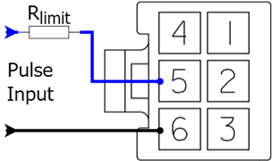
Pulse input for voltages higher than 5V
For example, a 12V Pulse signal provides:

Taking a resistor of 560Ω will suffice. It might not be accurate, but as 4V is the target, there will be sufficient leeway to take the closest 5% standard resistor value.
A 24V Pulse signal provides:

Therefore, a resistor of 1.5kΩ is required.
However, there might be another issue. The power dissipated in the resistor will then be 20V*14mA= 0.28W. This can be higher than a standard axial resistor, which usually has a maximum power dissipation of 0.25W. This can be resolved in one of two methods: use a resistor with an appropriate power rating or use multiple resistors to distribute the power dissipated by a single resistor.
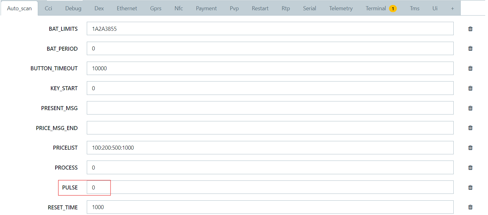
Pulse Settings
Pulse Settings can be edited within the MyPayter Terminal Management System.
Having selected a terminal, and entered configuration followed by Advanced Settings:
In the tab “PTOS” under the header “AUTO_SCAN” the setting to enable Pulse. The “PULSE” setting can turn on Pulse for a terminal in auto-scan configuration. This setting is a Boolean and turns it on when set to 1 and turns it off when set to 0.
The settings to configure the Pulse itself can be found in the tab “PTOS2” under the header “PULSE”.
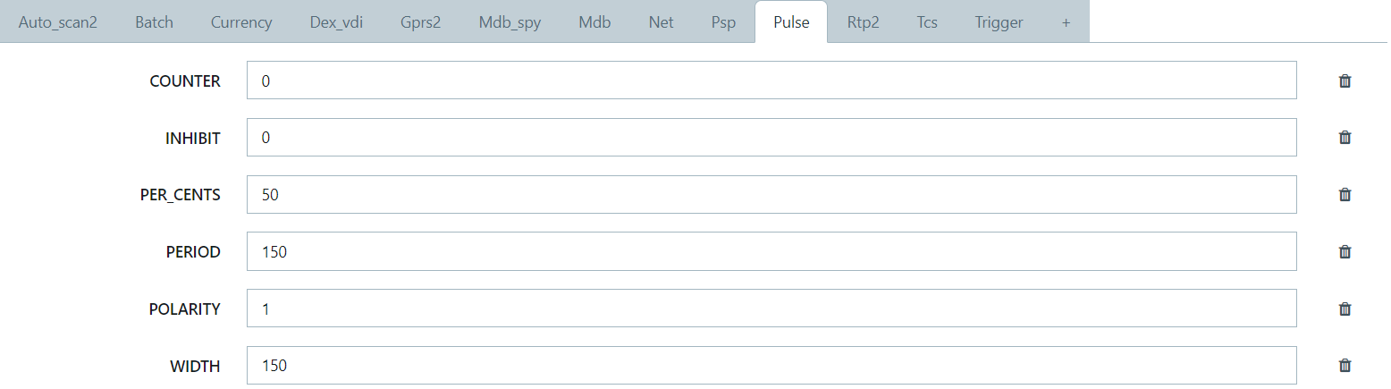
Setting Name | Type | Description |
|---|---|---|
| Integer | Defines the output pulse width in milliseconds. This setting only accepts whole numbers between 0 and 4,294,967,295 |
| Defines the number of cents each pulse represents (see PER_CENTS) | |
| Integer | Defines the ‘down’ time between consecutive pulses in milliseconds. This setting only accepts whole numbers between 0 and 4,294,967,295 (see PERIOD) |
| Boolean | Defines the output pulse polarity. 0 – Normally Open, output stays high and is pulled low for a pulse 1 – Normally Closed, output is pulled low and ‘released’ for a pulse (see POLARITY) |
INHIBIT | Integer | Defines whether to enable inhibit mode. 0 – Disable inhibit mode 1 – Enables inhibit mode, inhibits on a low voltage level 2 – Enables inhibit mode, inhibits on a high voltage level |
COUNTER | Integer | Defines whether to enable counter mode. 0 - Disable counter mode Other - Enable counter mode |
PER_CENTS
Based on this setting and the setting “DEFAULT_AMOUNT” under “PAYMENT” in the tab “PTOS”, this calculate s the number of pulses. If these settings are the same, only 1 pulse will be created. If “PER_CENTS” fits twice in “DEFAULT_AMOUNT”, 2 pulses will be sent for each transaction. If it fits three time then 3 pulses will be sent, etc.
PERIOD
This is different than WIDTH and does not describe the period of the pulses. How these two values create a pulse can be found in Pulse Output.
POLARITY
A terminal configured for Normally Closed will first start as Normally Open and will be set to Normally Closed during boot thus giving an initial invalid pulse.
FAQ
What is galvanically isolated?
Galvanic Isolation occurs when 2 electrical circuits are not electronically dependent on one another. If the ground of one circuit has a higher or lower voltage then the ground of the other circuit, they can still function as usual.
What is an optocoupler?
An optocoupler is an LED which activates a transistor with the light it emits. These 2 elements are put in a single component, so that any outside light does not activate the transistor. This means that applying the forward voltage on the LED input the transistor will activate and a current can flow from its collector to its emitter, therefore acting like a switch. As the relationship between the LED and the transistor is not electronically connected, but through light, the optocoupler can be used to galvanically isolate circuits.
What is meant by Normally Open/Normally Closed?
An electrically circuit can be considered either open or closed. An open circuit means that the electrical loop is interrupted somewhere, so no current can flow. A closed circuit however is not interrupted; therefore, a current will flow from the higher voltage potential to the lower voltage potential.
With Normally Open we mean that the circuit is usually open and can be closed on a certain action. This is typically describing a digital signal that gives a 1 in the usual case, while giving a 0 under a specific condition.
For Normally Closed is the circuit usually closed and opened on a certain action. This typically describes a digital signal that gives a 0 in the usual case, while giving a 1 under a specific condition.
What is meant by sink current?
Water is usually used as an analogy for electricity. Consider a faucet/tap as a controller of the (water) current for the higher water potential of the mains water supply. The water flowing from a faucet/tap will flow to a lower potential like a sink. If the sink can be controlled, it controls the flow from towards the lower/lowest potential. With a sink current we indicate the current flows towards the ground and not from the source. If a component is placed between the ground of the component and the actual ground, unintended behavior can occur.
Can a pulse be measured from the output with a multimeter?
Technically yes, but probably not.
Generally the pulse is too short to be visible on the display of an average handheld multimeter. With the pulse width configured to several seconds, then it should be possible to see the voltage change on the display during a pulse.
However if using a multimeter which shows measurements in time domain it will be trivial to see the pulse even if it is a few milliseconds short. These multimeters are usually not handheld and are in general a bit more expensive.
When switching a load, why use a P-channel MOSFET and not a relay?
A P-channel MOSFET is usually cheaper.
A relay includes internal mechanical components that can wear out, while MOSFETs do not. Therefore, a MOSFET will last longer.
This does not mean relays cannot be used, they are just not recommended and may limit Payter’s ability to provide support.
P6X Internal Diagram
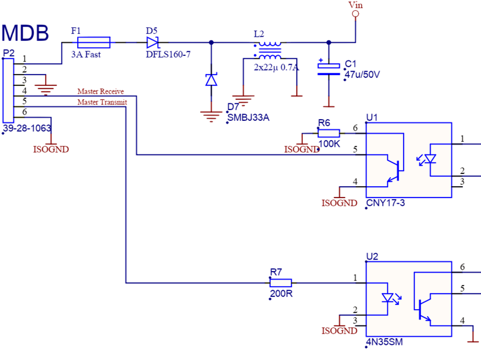
Schematic of the MDB port with the directly connected components