Apollo Pulse Settings
This chapter explains how to setup Pulse using the advanced settings. The settings are given for each of the 4 possible pulse modes, defining exactly what settings to configure for your application.
Basic Settings
When enabling the Pulse functionality in the AutoScan tab, this should automatically create a Pulse tab in the basic settings. This tab allows you to add output and input functionality to the terminal.
Pulse Modes
The Pulse functionality has 4 modes to support a range of different applications:
Single Pulse: The terminal will be configured to send a single pulse of a set duration upon successful transaction. This is often used when there’s just 1 product configured on the terminal.Pulse Per Cents: The terminal will be configured to send a certain amount of pulses for every X cents received. This can be used for applications where the amount of pulses depends on the price of the product.Pulse on ID: Determine amount of pulses using a setting. Used often when there’s 1 pulse for the first product, 2 pulses for the second product etc. This is used when the amount of pulses doesn’t depend on the price of the product.Timed Activation: Instead of varying the amount of pulses, the duration of the pulse is altered. This can be used e.g. when enabling a device for a certain amount of time.
Setting Name | Type | Description |
|---|---|---|
| Drop-down | Decides in what mode the terminal will operate. |
| Integer | The amount for each pulse, e.g. 50 cents. The price of the product must be a multiple of this number. Ignored if not in |
Output Profiles
Output profiles contain all necessary information about an output. It determines the duration of pulses, the amount of pulses and the output pin that a pulse should be activated on. It is connected to a specific product by matching the product’s Product Reference with the profiles Reference setting.
Setting Name | Type | Description |
|---|---|---|
| String | Match the |
| String | Name of the output pin as printed on the pulse board, e.g. “RLY1”. |
| Integer | Duration of the active period of a pulse in ms, a minimum of |
| Integer | Duration of the inactive period of a pulse in ms |
| Integer | Number of pulses to give. |
Input Profiles
Input profiles allow for inhibiting a certain product, or all products, from becoming active. This is useful when a device has a “busy” or “out of order” signal.
If all products are inhibited, the terminal will show a “inhibit screen” instead of a payment screen or product selection screen. The title and subtitle for these screens can be adjusted in the Apollo Autoscan Settings.
Setting Name | Type | Description |
|---|---|---|
| String | Match the |
| String | Channel to attach inhibit line as printed on the pulse board, e.g. “Chn1” or “INP1“. |
| Boolean | Set to true if inhibit is pulled up, meaning it is active when the signal is low |

Example of an inhibit screen
Hardware
This paragraph provides information about the Pulse board's timing, electrical characteristics, and physical dimensions.
Connections
Relays
This section explains how the relays on the output of the pulse board work.
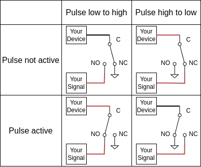
Normally Open and Normally Closed
The terms “Normally Open” and “Normally Closed” can be confusing to someone that isn’t familiar with them. Both terms refer to the state of a switch; either “opening” or “closing” the circuit:
An “open circuit” means that the wires of the circuit will NOT be connected by the switch, meaning no current can flow. Most would consider the switch to be “off”.
A “closed circuit” means that the wires of the circuit WILL be connected by the switch, meaning a current can flow from the input to the output of the switch. Most would consider the switch to be “on”.
Connecting the Relays
Connecting the relays can be done in many different ways, but we generally recommend connecting the device receiving the pulse to “C”, and connecting the voltage and GND wires to “NO” and “NC” depending on the pulse the connected device expects.
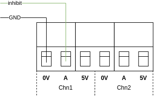
Inhibit input
In order to use the inhibit input, connect the signal to the “A” port and the device’s GND to the “0V” port of the device. The maximum voltage is 5V.
Timing
The shortest pulse that the pulse board can generate is 10ms. The board has an accuracy of +-1ms.
Electrical characteristics
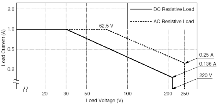
Output
The image below shows the power rating for the board's output. To ensure the longevity of the Pulse board, it's crucial to keep both current and voltage within the solid line for DC loads or within the dotted line for AC loads. Exceeding these limits can significantly reduce the board's lifespan.
Inhibit input
The board’s inputs are able to withstand a maximum voltage of 5V.
If unable to provide a signal with a maximum voltage of 5V, there is the option to utilize the 5V output available on every input channel. This can be routed this output back to the input port with a relay in-between. This configuration enables users to toggle the inhibit signal on and off by controlling the relay, effectively managing the inhibit function as needed.
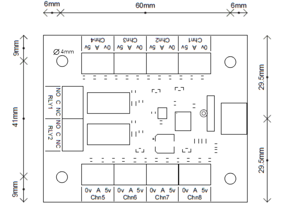
Physical dimensions
The board's physical dimensions are 59mm by 72mm, and it's designed for secure mounting using four 4mm screw holes. This setup makes it easy to install and secure the board in the desired location.
External devices are connected to the Pulse board using screw terminals. Please refer to the table below for guidance on the appropriate wire to use:
Conductor cross section | 0.3mm² to 1.3mm² |
AWG | 22 to 16 AWG |
Strip length | 6mm |